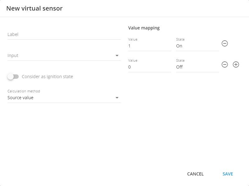
Virtual sensor interface
Virtual sensor interface
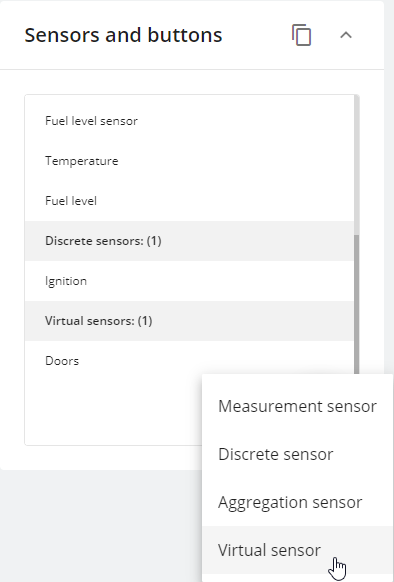
Virtual sensor adding in sensors and buttons
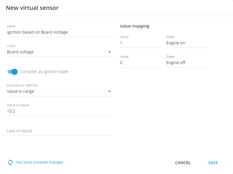
Example configuration for virtual ignition
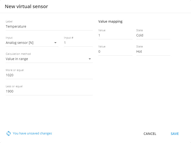
Example configuration for reading temperature from analog sensor
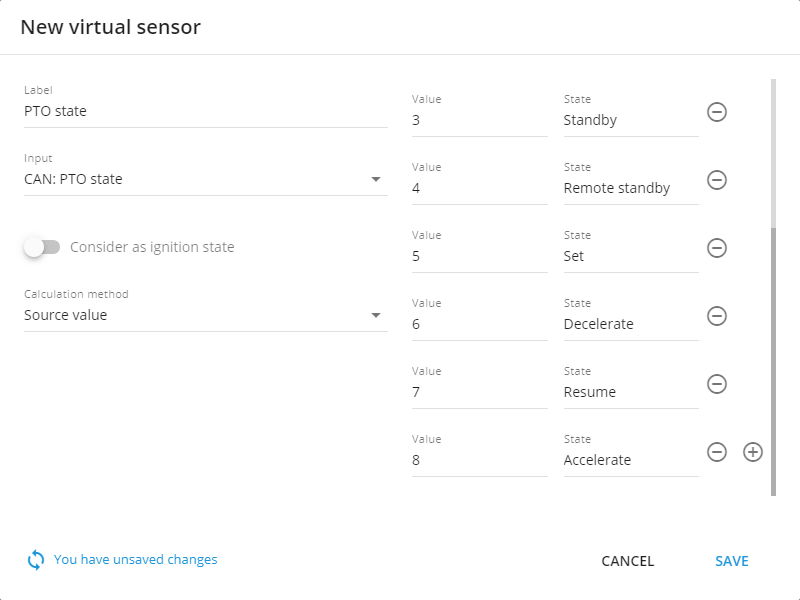
Configuration example for source value calculation method
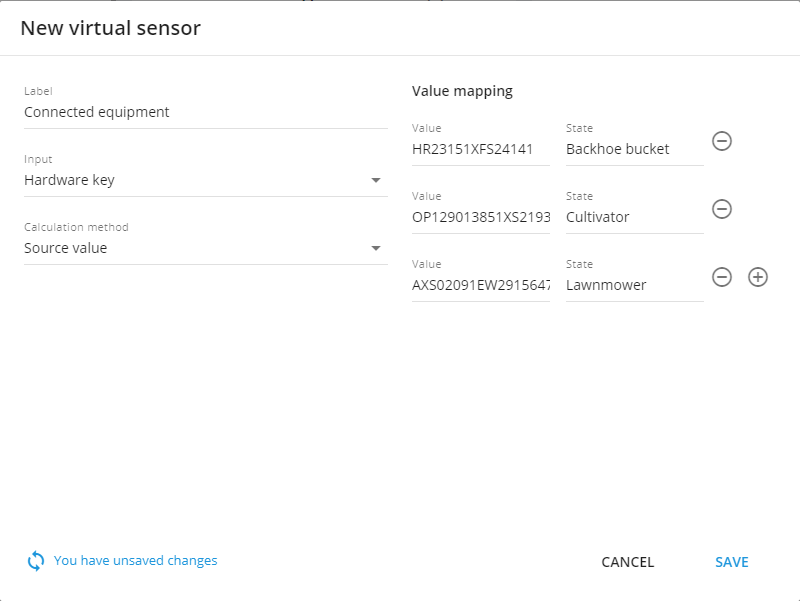
Configuration example for source value calculation method for hardware key or state field sensor reading
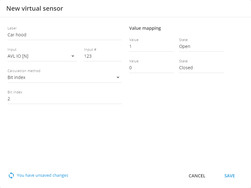
Configuration example for Bit index calculation sensor